Showing posts with label watt. Show all posts
Showing posts with label watt. Show all posts
Friday, October 31, 2014
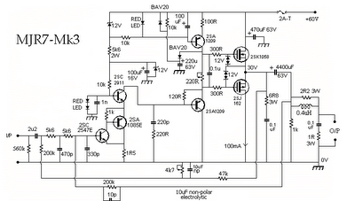
The monophonic 270 watt Double barreled Amplifier

This amplifier is the monophonic 270 watt Double barreled Amplifier. For the original article, I specified plus and minus 85 V dc power supply voltages. The voltage can be increased to about 93 V to obtain a power rating of 300 W. The amplifier can be built either as a stereophonic or a monoponic unit. My original amps were mono units because the heat sinks, transformer, and filter caps that I used were too large for a stereo amp.
The circuit described on this page is a modification of the original Double Barreled Amplifier. The circuit has been simplified somewhat. The circuit board layout is smaller and much more compact. The driver transistors now mount on the circuit board instead of on external heat sinks. And the circuit has the feedforward compensation that I describe for the Low TIM Amplifier.
If you build this amplifier, you must keep the wiring between the heat sinks and the circuit boards as short as possible if you dont want oscillation problems.
When you test the circuit boards before connecting the power transistors, temporarily connect a 10 ohm resistor in series with a 0.1 ufd capacitor from the loudspeaker output to the power supply ground.
The Circuit Boards
I do not have circuit boards for the Double Barrelled Amplifier. If you wish to build it, you must make your own. Two drawings show the parts layout on the board, one with circuit traces and one without. These are scaled by a factor of 1.5. The other shows the circuit traces only. All layout views are from the component side of the board. You must flip the layout for the foil traces over to obtain the solder side view. The circuit board measures 4 inches by 6 inches. To my knowledge, there are no errors in the layout. If you decide to use it, you should carefully check it for errors because I could have easily made a mistake.
I do not recommend that you make the circuit boards unless you have experience in doing it. A source of materials for making your own printed circuits can be found here. I have been told that their "Press and Peel Blue" product (not the wet stuff they sell) can be used to successfully make boards with traces as narrow as 0.01 inch. The smallest traces on the amplifier layout are 0.03 inch wide. The PnP Blue product is basically a transfer medium that allows you to transfer the toner image from a laser printer directly onto bare copper clad board and then etch it in FeCl3 (ferric chloride).
After you etch the board, the copper should be cleaned with steel wool, lightly coated with solder flux, and then "tinned" with a soldering iron and rosin core solder. Do not use a commercial tinning solution that you dip the board into. It is almost impossible to solder a board that is tinned with one of these products because they corrode very quickly. When you drill the board, you should use the correct size drill bit for the pads. The hole diameters I recommend are: small pads - 0.032 inch, medium pads - 0.040 inch, large pads - 0.059 inch, mounting holes - 0.125 inch. If you do not use a sharp drill bit, you can pull the pads off the board when you drill it.
Circuit Description
If you compare the Double Barreled circuit to the Low TIM circuit, you will see a lot of similarity between the two. Indeed, there is a Low TIM Amplifier embedded in the Double Barreled Amplifier. The major difference between the two is that transistors are added in series with those in the Low TIM circuit to form the Double Barreled circuit. By doing this, the voltage across the transistors is decreased so that the power supply voltage can be increased for higher output power.
Basically, the circuit description for the Low TIM Amplifier also applies to the Double Barreled Amplifier. The major difference between the two is the addition of transistors Q22 through Q31. Q22 is connected as a common base stage at the output of Q12. The two transistors form a cascode stage. The base of Q22 connects to the junction of R52 and R54. These two resistors are equal and are connected as a voltage divider between the loudspeaker output and the positive rail. This forces the base voltage of Q22 to float half way between the loudspeaker output voltage and the positive power supply rail. Similarly, Q13 and Q23 form a cascode stage. R53 and R55 force the base of Q23 to float half way between the loudspeaker output voltage and the negative power supply rail. The addition of Q22 and Q23 cause the collector to emitter voltages of Q12 and Q13 to be approximately one-half of what the voltages would be without Q22 and Q23.
Transistors Q24 and Q25 connect in series with the pre-driver transistors Q14 and Q15. The base of Q24 floats half way between the output voltage and the positive rail. The base of Q25 floats half way between the output voltage and the negative rail. The addition of Q24 and Q25 cause the voltages across Q14 and Q15 to be approximately one-half of what they would be without Q24 and Q25. Similarly, transistors Q26 through Q31 cause the voltages across Q16 through Q21 to be approximately one-half of what they would be without Q26 through Q31. By connecting the transistors in series in this way, the rail voltages can be increased for higher output power.
The basic construction details of the Low TIM Amplifier also apply to the Double Barreled Amplifier. There are two short circuit jumper wires that must be soldered on the circuit board. These are marked with a J on the layout. In addition, you must solder a short circuit jumper in place of C6B if you use a non-polar capacitor for C6A. This is explained in the parts list for the Low TIM Amplifier. Because there are eight output transistors, two main heat sinks per channel are required. Q18, Q20, Q28, and Q30 should be mounted on one and Q19, Q21, Q29, and Q31 on the other. Resistors R61 through R64 and wires connecting the collectors of Q18 and Q20 and the collectors of Q19 and Q21 mount on the heat sinks. These connect between lugs on the transistor sockets. The four bias diodes D1 through D4 can be mounted on either heat sink. It is not necessary to divide the diodes between the two heat sinks because both heat sinks will operate at the same temperature. I recommend setting the voltage across Q7, i.e. the voltage between the collectors of Q22 and Q23, so that that amplifier is biased at 120 mA. This will give the same quiescent power dissipation per heat sink as in the Low TIM Amplifier.
Testing the Circuit Boards
After you solder the parts to the circuit board, it is tested using the same procedure specified for the Low TIM circuit board. First, you must solder the short circuit jumper across Q7 and you must solder the 100 ohm 1/4 W resistors from the loudspeaker output to the emitters of Q16 and Q17. If you dont have a bench power supply that puts out plus and minus 85 to 93 V dc, you can test the circuit board at a lower voltage. I would prefer test voltages of at least plus and minus 50 V dc. An option is to connect bench power supplies in series to obtain the plus and minus 85 to 93 V dc. I have routinely connected two 40 V Hewlett Packard power supplies in series with the positive and negative outputs of a Hewlett Packard 50 V dual power supply, and I have never had any problems. To protect the circuit boards, you might want to put a 100 ohm 1/4 W resistor in series with the plus and minus power supply leads for the tests. The current drawn by the circuit should be low enough so that the voltage drop across these resistors is less than 1 V if nothing is wrong on the circuit board. There are 2 ground wires from the circuit board. Both must be connected when testing the boards.
I cant stress how important it is to be careful in testing a circuit board. Even simple errors can cause the loss of many expensive transistors. I always use current limited bench power supplies to test a circuit board before and after connecting the power transistors. I also bias an amplifier using current limited power supplies in place of the amplifier power supply. When I initially power up an amplifier with its own power supply, I always use a Variac variable transformer to slowly increase the ac input voltage from 0 to 120 V rms while observing the amplifier output on an oscilloscope with a sine wave input signal. If I see anything wrong on the oscilloscope, I turn the Variac to zero and try to diagnose the problem using the bench power supply. I never use a load on the amplifier for these tests.
Parts List
With the following exceptions, the parts for the Double Barreled Amplifier are the same as for the Low TIM Amplifier.
Capacitors
C10, C11 - 15 pF mica
C13, C14 - 100 uFd 100 V radial electrolytic
C21, C22 - 47 uFd 100 V radial electrolytic
C26, C27 - 270 pF mica
C28 - 0.01 uFd 250 V film
Transistors
Q1, Q2, Q5, Q7, Q9, Q10 - MPS8099 or MPSA06
Q3, Q4, Q6, Q8, Q11 - MPS8599 or MPSA56
Q23, Q24 - 2N3439
Q22, Q25 - 2N5415
Q26 - MJE15030
Q27 - MJE15031
Q28, Q30 - MJ15003
Q29, Q31 - MJ15004
Diodes
D5, D6 - 1N4934 fast recovery rectifier
D13 through D16 - 1N5250B 20 volt zener diode
Resistors
R13, R14 - 5.6 kohm 1 watt (This value is for 85 V power supplies. For other power supply voltages, the formula is on the Parts List page for the Leach Amp.)
R28, R29 - 200 ohm 1/4 watt
R30, R31 - 3.9 kohm 1 watt
R37 through R40 - 470 ohm 1/4 watt
R41 through R44 - 10 ohm 1/2 watt (changed 6/27/00)
R52 through R55 - 6.2 kohm 1 watt
R56 through R59 - 10 ohm 1/2 watt (changed 6/27/00)
R60 - 39 ohm 1/4 watt
R61 through R64 - 0.33 ohm 5 watt. These 4 resistors are mounted on the heat sinks between solder lugs on the power transistor sockets. The wires that connect the collectors of Q18 and Q20 and the collectors of Q19 and Q21 are also soldered between the lugs on the sockets. Keep all leads as short as possible and use insulation stripped from hookup wire around the bare leads of the resistors.
R65, R66 - 300 ohm 1/4 watt
Wednesday, October 29, 2014
600 Watt Quasi Amplifier With Mosfet IRFP460
ACTK 400/600 Watt
Two versions of a robust module capable of delivering high powwer for extended periods. The Actrk400 uses 6 n-channel Mosfets in the output stage to deliver around 400 watts into 4 ohms while the Actrk600 uses 12 n-channel Mosfets in the output stage to deliver power in excess of 600 watts into 4 ohms. One constructor has achieved almost 900 watts with the Actrk600 layout using 12 IRFP460 Mosfets.


 ACTK Power Supply
Schmatic
 Layout power supply

Final Set up And Adjustment
No attempt should be made to set up or test a power amplifier module that is not correctly mounted on
a heatsink. Make sure the main power supply is fused and the work area is clear. First check all your
work and make sure the output devices are insulated from heatsink. The set up is done without an
input or a load connected to the power amplifier.
1. Check the power supply is operating correctly and verify the rail voltages. Switch the power
supply off and check with a multimeter that the rail capacitors have discharged.
2. Using a multimeter measure the resistance of VR2 and set it for maximum resistance.
3. Correctly connect the ground lead, the two positive leads plus the negative lead to the power
amp module.
4. Remove the PCB fuses and replace with 100 ohm 5 watt resistors. Connect a multimeter that
is set to the 20 volt scale across the positive rail 100 ohm resistor.
5. Check that the power supply connections are correct one last time and switch on. If the
multimeter reading goes off-scale, turn off immediately and find the problem. Check also the
100 ohm 5 watt resistors; they may have gone open cct.
6. If everything seems ok adjust VR2 to set the output stage bias current, by measuring the
voltage across the positive rail resistor. Adjust for a reading of 4 volts per output FET pair. I.e.
For a 6 FET board set for a voltage of 12 volts. This equates to a bias current of 40mA per FET
pair or 120 mA total. For the 12 FET board set for a voltage of 24 volts.
7. If everything seems ok, check the output offset voltage and adjust VR1 to achieve an offset of
less than 10 mV. You will need to wait briefly between adjustments for the offset to settle.
8. All being well switch off, back off the bias control trimmer (VR2) and replace the 100 ohm
resistors with 10 ohm 1 watt resistors. Switch on again and re-adjust VR2 to get 0.4 volts per
FET pair.
9. Switch off, remove the resistors and put the fuses back in. Switch on, re-check the offset
voltage and adjust with VR1 if necessary.
The amp module is ready, connect the input and output and enjoy.
Read More..
Two versions of a robust module capable of delivering high powwer for extended periods. The Actrk400 uses 6 n-channel Mosfets in the output stage to deliver around 400 watts into 4 ohms while the Actrk600 uses 12 n-channel Mosfets in the output stage to deliver power in excess of 600 watts into 4 ohms. One constructor has achieved almost 900 watts with the Actrk600 layout using 12 IRFP460 Mosfets.
Actrk 600W schematic
ACTK 400W Layout
ACTK 600W Layout
Schmatic
Final Set up And Adjustment
No attempt should be made to set up or test a power amplifier module that is not correctly mounted on
a heatsink. Make sure the main power supply is fused and the work area is clear. First check all your
work and make sure the output devices are insulated from heatsink. The set up is done without an
input or a load connected to the power amplifier.
1. Check the power supply is operating correctly and verify the rail voltages. Switch the power
supply off and check with a multimeter that the rail capacitors have discharged.
2. Using a multimeter measure the resistance of VR2 and set it for maximum resistance.
3. Correctly connect the ground lead, the two positive leads plus the negative lead to the power
amp module.
4. Remove the PCB fuses and replace with 100 ohm 5 watt resistors. Connect a multimeter that
is set to the 20 volt scale across the positive rail 100 ohm resistor.
5. Check that the power supply connections are correct one last time and switch on. If the
multimeter reading goes off-scale, turn off immediately and find the problem. Check also the
100 ohm 5 watt resistors; they may have gone open cct.
6. If everything seems ok adjust VR2 to set the output stage bias current, by measuring the
voltage across the positive rail resistor. Adjust for a reading of 4 volts per output FET pair. I.e.
For a 6 FET board set for a voltage of 12 volts. This equates to a bias current of 40mA per FET
pair or 120 mA total. For the 12 FET board set for a voltage of 24 volts.
7. If everything seems ok, check the output offset voltage and adjust VR1 to achieve an offset of
less than 10 mV. You will need to wait briefly between adjustments for the offset to settle.
8. All being well switch off, back off the bias control trimmer (VR2) and replace the 100 ohm
resistors with 10 ohm 1 watt resistors. Switch on again and re-adjust VR2 to get 0.4 volts per
FET pair.
9. Switch off, remove the resistors and put the fuses back in. Switch on, re-check the offset
voltage and adjust with VR1 if necessary.
The amp module is ready, connect the input and output and enjoy.
Thursday, October 23, 2014
70 Watt MOSFET Audio Amplifier
This is use the MOSFET power amplifier circuit, amplifier circuit has a very good sound quality. With the noise is quite small, thus making the amplifier circuit is suitable for you to try. Heres the circuit.
 |
| Click to view larger. |
Friday, October 17, 2014
2 Watt FM Transmitter
CIRCUIT DESCRIPTION
The circuit is basically a radio frequency (RF) oscillator that operates around 100 MHz. Audio picked up and amplified by the electret microphone is fed into the audio amplifier stage built around the first transistor. Output from the collector is fed into the base of the second transistor where it modulates the resonant frequency of the tank circuit (L1 coil and the trimcap) by varying the junction capacitance of the transistor. Junction capacitance is a function of the potential difference applied to the base of the transistor T2. The tank circuit is connected in a Hartley oscillator circuit.
Components List
R1=220K R2=4.7K R3,R4=10K R5=100ohm | C1,C2=4.7uF Electrolytic C3,C4=1nF C5=2-15pF C6=3.3pF | Q1=BC547C Q2=BD135 P1=25K MIC=Electret Condenser Type |
Sunday, September 7, 2014
600 Watt Quasi Amplifier With Mosfet IRFP460
ACTK 400/600 Watt
Two versions of a robust module capable of delivering high powwer for extended periods. The Actrk400 uses 6 n-channel Mosfets in the output stage to deliver around 400 watts into 4 ohms while the Actrk600 uses 12 n-channel Mosfets in the output stage to deliver power in excess of 600 watts into 4 ohms. One constructor has achieved almost 900 watts with the Actrk600 layout using 12 IRFP460 Mosfets.
| 600 Watt Quasi Amplifier With Mosfet IRFP460 |
Friday, August 29, 2014
Simple 30 Watt VHF Amplifier by using 2SC1946A
The 30 watt amplifier schematic shown below provides an appropriate power boost with an input of 4 watt up to 6 watts. The schema is designed to cover 88-108MHz FM Broadcast Band. However, the schema is very stable at my place and provides a clean-output through seven (7) element Butter-worth low-pass filter.
Simple 30 Watt VHF Amplifier Circuit Diagram:

Notes:
The heart of the schema is 2SC1946A VHF RF power transistor. The transistor is specifically designed for operation in frequencies up to 175 MHz, with very good results. As you can see, the power line is well decoupled. The amplifier current can be over 5 amps. All the coils are made from 16gauge laminated wire (or Silver copper wire can do best) and the RFC can be of HF toroid core (as shown in the picture) or 6 holes ferrite bead.C3 and R1 forms snubber schema while R2 and C6 prevent the amplifier from self-oscillation at VHF, sometimes you need to add 180 ohms in parallel with L7.That will cause the amplifier to dissipate UNDESIRABLE VHF thereby reducing spurious level.

The photo below is 60Watts VHF power amplifier using the above schema. Two of 2SC1946A transistors are arranged at 90 degrees to each other and their outputs are combined using "Power Combiner Network”. It is quite difficult to combine powers at VHF and UHF bands.
However, I recommend that hobbies should stick to single power design due to its complicity and large rate of INTERFERENCE. (in attempt to go for double transistors which involves power combiner network). Since the two amplifiers are operating in different phase (out of phase).
Tuning:
Tuning of the amplifier is not hard at all. You just have to connect the output to a good antenna with a transmission line (RG214) of 50 ohms. First match the output network, and then do the same to the input network for a maximum power output. By way of adjustment, you can increase the output at its operating frequency.
Simple 8 Watt Audio Power Amplifier Schematic
Here is the schematic for an 8 watt audio power amplifier. This amp can be used as a simple booster, the heart of a more complicated amplifier or used as a guitar amp. It is very small and portable unit and can be powered through 12V battery. I built the schema on a Vero Board and had to add extra inductors, capacitors and resistors to prevent oscillation.
8 Watt Audio Power Amplifier Schematic

8 Watt Audio Power Amplifier Circuit Diagram
Parts:
R1 = 47K
R2 = 2.2R/1W
R3 = 220R/1W
R4 = 2.2R/1W
C1 = 100nF-63V
C2 = 10uF-25V
C3 = 470uF-25V
C4 = 2000uF-25V
C5 = 100nF-63V
IC1 = LM383
SPKR = 4ohm/8W
Notes:
- IC1 must be installed on a heat sink.
- C1 is for filtering and to prevent oscillation and should not be omitted.
- The schema can be built on a Vero Board, universal solder board or PC board, the PC board is preferred.
- The schema draws about 880Ma at 12 V.
- By swapping the values of R2 and R3; you can turn this amplifier into a guitar amp with no preamp required.
- If you cant find 2000uF, then replace C4 with a 2200uF unit.
- If you add a 0.2uF capacitor in series with a 1 ohm resistor to the output you can prevent oscillation of the schema under certain conditions.
Monday, August 25, 2014
2 3 Watt Low audio power amplifier
These amplifiers using IC KA2202 and KA2207, which has a power output of 2.3 Watt berimpedansi 4 ohms. Minimum supply voltage and maximum 5Volt 20Volt. See schematics and component list below.
Part List
R1 = 100K
R2 = 56R
R3 = 56R
R4 = 1R
Use 1/4 Watt resistor
C1 = 100uF
C2 = 100uFC4 = 100uF
C5 = 470uFC6 = 100nF
C7 = 470pFC8 = 2,2nF
C9 = 100uF
U1 = KA2202 , KA2207
Subscribe to:
Posts (Atom)
