Sunday, August 31, 2014
Stereo balance indicator

Imagine the scheme stereo balance indicator. It has 3 LEDs showing the predominance of right or left channel, or they are the same level.
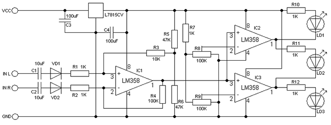
Through a chain consisting of C1, VD1, R1 left and C2, VD2, R2 for the right channel signal supplied to the operational amplifier IC1 is enabled by the differential amplifier circuit. The output of IC1 is supplied to a signal noninverting inputs of IC2 and IC3. Will prevail if the right channel outputs IC2 and IC3 will have a high level and lights LD3. Otherwise would prevail if left channel outputs IC2 and IC3 will be low and lights LD1. If the signal levels are the same, the outputs of IC2 and IC3 will have a correspondingly high and low levels, and turns LD2. IC1, IC2, IC3 can apply the type LM358 or 741. Electrolytic capacitors for voltage 16V. LEDs any thin, preferably of different colors. Supply voltage 15-30V.
The whole setup is reduced to install IC2 and IC3 balance by adjusting the R8 and R9.
Original article source cxem.net
Subscribe to:
Post Comments (Atom)
No comments:
Post a Comment