Thursday, November 20, 2014
Audio Frequency Generator Circuit
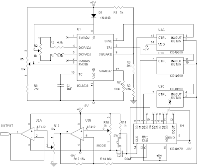
Audio Frequency Generator or often known by AFG is a device electronics used to generate signals with audio frequency range. Audio Frequency Generator (AFG) in the market there are many variant, from the analog to the digital . Even the assembly also exists, in principle, AFG is the frequency generator with an audio range. Here is one set of Audio Frequency Generator (AFG) which can be a reference if you want to make a series of Audio Frequency Generator (AFG) . The series of Audio Frequency Generator (AFG) is to use IC L8038 as a signal generator it.
 |
| AFG |
The series of Audio Frequency Generator (AFG) above has three output waveform that is, sine, square and triangle directly from the IC L8038. IC CD4066 and IC circuit Cd4017 a configuration circuit for waveform selector that can be set by pressing SW1. To adjust the working frequency is set by potentiometer R2.
2 Transistor Line Follower Robot
Make a line follower robot can be done with two transistors. Line Follower Robot series is one of the two transistors contor robot line follower circuit is in Bagun with two NPN transistor and the motor driver as well as processing of sensor signals.
In the circuit of line follower robot consists of two parts of the same, only different functions for the motor driver the right and left. Sensor circuit of line follower robot uses the LDR and LED. LDR sensor sensitivity can be set with the VR 10 is mounted in series with the LDR. For more details, see the following figure.
In the circuit of line follower robot consists of two parts of the same, only different functions for the motor driver the right and left. Sensor circuit of line follower robot uses the LDR and LED. LDR sensor sensitivity can be set with the VR 10 is mounted in series with the LDR. For more details, see the following figure.
Line Follower Robot series 2 Transistor
The working principle of the motor driver circuit between the right and left together, when the LDR get the reflection of light from the LED LDR resistance will decrease and make the transistor saturation and motor gets supply and rotates so that the robot moves forward. So at the moment is not the case then the motor did not get a supply, for example, only one sensor is exposed line and make the LDR did not receive the reflected light is then Motr in the stationary and the other motor rotates and makes the LDR are back in the reflection of light and the robot moves forward again.
Line Follower Robot
Wednesday, November 19, 2014
Adapter power supply and charger circuit
Basically adapter, power supply and charger circuit has a similar construction which consists of a transformer, rectifier (rectifier) and smoothing the voltage. For there is usually an additional power supply voltage stabilizer of voltage regulator IC LM series 78XX or 79XX .
Below is a schematic circuit adapter, power supply, or battery charger (for gadgets, mobile phones, MP4player, smartphone) that is equipped with a 5V voltage stabilizer:
| Adapter, power supply and charger circuit |
USB SPDIF DAC with IC PCM 2902
The tool that I made and I discuss in this article I give the name USB SPDIF DACEvery word in the name corresponds to the function of the tool that I made this.
USB, this device serves to take the music information in digital form from a computer via the USB port
SPDIF, this tool can output digital music information received through the USB port, through the SPDIF output terminal that is also present in this device, so if you have a DAC that does not have a USB input, you can still use and do not need to buy a new DAC that has an input USB.
DAC, this tool can convert the digital signals derived from the USB port, an analog signal, which you can connect to the amplifier to the ahirnya you can hear the speaker
Scheme of the USB DAC can be seen in Figure 1 below.USB, this device serves to take the music information in digital form from a computer via the USB port
SPDIF, this tool can output digital music information received through the USB port, through the SPDIF output terminal that is also present in this device, so if you have a DAC that does not have a USB input, you can still use and do not need to buy a new DAC that has an input USB.
DAC, this tool can convert the digital signals derived from the USB port, an analog signal, which you can connect to the amplifier to the ahirnya you can hear the speaker
 |
| Click to view larger. | Figure 1 |
As you can see on the schematic in Figure 1 above, which is the heart of the circuit is IC USB DAC PCM2902 made by Texas Instrument, other than that I also added a digital SPDIF output isolation transformer on from this series. 2902 PCM encoding decoding work on the principle that generally abbreviated as word CODEC.
The new circuit will work when the USB input port terminal in the circuit connected to the computer, at this voltage 5V on the USB port of any computer will be triggering the circuit to begin work, and vice versa when the computer is turned off then the circuit will be in standby mode to wait until there is more tension 5V from USB port of computer.
When the received voltage is 5V USB port the computer then the circuit will begin to receive the digital data files during the grace period of 1 ms, all data received during the period of time of 1 ms is called a frame, the data in the first frame is stored in a memory buffer that is in the PCM2902, then the circuit will start the second frame as well as long lead times for 1mS, 1mS a second after the first data from the file will be converted into analog signals for analog terminal is then removed through out the pin 15 and 16 of the PCM2902, other than that this digital signal simultaneously will also excreted through the DOUT terminal pin 25 of the PCM2902 DAC to be connected to older products that do not have a USB input terminal.In addition to functioning as a DAC, PCM2902 actually also has other functions such as setting volume level and ADC, but the circuit that I developed is only aimed for the ADC and the conversion from USB to SPDIF.
Proposed Power Supply For USB SPDIF DAC
Power Supply that I use in this project using the configuration has been proven able to tame the hum in the tube 26, the power supply has karakater very stable, low noise and low impedance, but complicated to make, so for the purposes of this project I recommend another series that is not as complicated Heater power supply 26, but the quality is still better than most of the power supply kit used in the DAC in general, Figure 2 below is the recommendation power supply for USB DAC this project.
 |
| Click to view larger. | Figure 2 |
1. Diode bridge and capacitor input filter
2. TL431 as the reference voltage
3. OP Amp OP27 as the error amplifier
4. BD139 transistor as a pass transistorThis configuration is basically the general configuration of a linear regulator series, very much the regulator IC using this configuration, but the circuit in Figure 2 above has several advantages that are not owned by the regulator circuit in the form of ICa) high stability, since it uses a reference voltage source of good quality is TL431, and therefore not in a package with a pass transistor, the heat of the pass transistor can not seep into the source of reference voltage and makes it unstable, this sort of thing happens in IC voltage regulator.b) Using the Op Amp high quality, which in this case OP27, so it is not easy to oscillate as the OpAmp used in the regulator IC.c) If there is a chance you could also replace the TL431 or OP27 Op Amp voltage source and another that is expected to be better than either of these components.
 |
| Series of the finished PCB, top view |
 |
| IC PCM2902 |
Tuesday, November 18, 2014
Different types of TV TUNER
TV tuner that is used on older models and new models of television there are some differences. Therefore, understanding the different types of tuner would be useful if we want to replace the tuner with the other models.
Supply voltage tuner.Tuner older models generally use a supply voltage of 12v, the new models are commonly used 5V supply voltage. Some use a 9V voltage, but very rare.
| TV TUNER |
Voltage Synthesizer tuner (VS tuner)
Tuner that uses a tuning control (VT or BT) with a voltage between 0 to 33V Voltage Synthesizer tuner named. TV can be found on the aircraft models, old and new
Based on how the control band-switch, Tuner VS then there are 2 kinds, namely
Using 3-Band input sw, the VL-VH-U
Using 2-Band input sw, the Band SW1 and SW2 Band. This tuner is actually similar to the type of band 3-sw. For control-sw 2 band is in the tuner will still be converted into 3-sw bands.
Frequency Synthesizer tuner (FS tuner) or the type of PLL
Tuner wherein the tuning voltage and the voltage controlled band switching the digital communication through SDA and SCL. This tuner has a supply voltage Vcc, which is
5V is used for the digital tuner circuit control and
33V (fixed voltage or fixed) is used to control the voltage supplied to the tuning in the digital circuits within the tuner.
(Tuner old) sometimes there are additional circuit voltage of 12V to the tuner.
Frequency band.
Based on the wide range of revenue-frequency band, there are three kinds of tuner
Normal tuner
Superband tuner
Tuner hyperband
Normal tuner, the tuner that can receive broadcasts "on-air" (terrestrial) TV in the frequency band:
- Frequency of VHF Band I - VL 41-68 Mhz
- Band III - VH 174-230 Mhz
- Frequency UHF Band IV - U 470-581 Mhz
- Band V - U 582-960 Mhz
- Band II 87.5 - 104 MHz is used for FM radio broadcasting
- VL and VH bands used for broadcast channels 2 through 12
- U bands used for broadcast channels 21 to 69
Superband Tuner and Hyperband, the tuner can receive broadcast as normal tuner plus the ability to receive broadcasts "off air" CATV (cable television).
- S band using frequency band between VL and VH
- H-band using a frequency band between VH and U
- Superband Tuner can receive the broadcast band S
- Hyperband tuner can receive broadcast band and S band H
Based on the IF frequency out
IF frequency tuner out there who have 38/38.9/45.75 Mhz frequency. In Indonesia generally use 38.9Mhz frequency, but sometimes there is a use 38.0Mhz
Based on the pin-out
There are several kinds of tuner long pin-out configuration. But now almost all the tuner is already using an international standard 11-pin
Universal tuner
China is now producing "universal tuner" 11-pin. Indonesia was just the market we do not know whether it exists or not. This tuner can be used to substitute for the various types of tuners and tuner can adjust to this direct voltage of 5, 9, or 12v.
RF antenna input connector
Form the antenna input connector there are two kinds, namely:
- RCA type connectors
- Antenna RF connector
Tuner modules
Tuner is a tuner module inside there are all Video IF amplifier circuit and the FM-detector. This kind of tuner is using VS and some are using the FS.
Tuner module has output like:
- RF AGC-out
- RF AFC-out
- Audio-out
- Video-out
- Base band out, the signal to be processed into stereo sound circuit.
Except that in tuner is also sometimes diperlengkapa with audio-switch to TV / AV-in. Therefore, to the sound of the AV-in connected via Audio-in found on the tuner module. Sometimes the sound volume to be controlled in the tuner module.
- SONY tuner module 1
- SONY tuner module 2
- Toshiba tuner module
Impedance input / output
Impedance tuner has all kinds of input / output 75 ohm.
How to distinguish 2-band tuners VS sw with PLL tuner FS
In all these circumstances and the removable pin 11 feet was not cut, it is sometimes difficult to distinguish between two band-tuner tuner sw with FS.
Some models have a tuner pin legs partially emptied. FS Tuner has a location pin 30V voltage 3 numbers from the back (of the IF pin out).
Non Latching Momentary Switches

The most common are push-button, but toggle switches too may be spring-loaded to return to one position after activating. In the catalogues, an (ON)-OFF description means its only ON while youre holding the lever in place. With push-button, theyre more often described as momentary-on (push to make) or momentary-off (push to break). Heres how the two types could be used together to control ON-OFF action by latching a relay, a very common system on industrial control gear. The relay needs to have two or more poles (the switches) which can be change-over (double-throw) or single-throw types.
The "On" switch S2 is a push-to-make (momentary on) type, and allows power through to the relay coil when pressed. This becomes an electro-magnet and pulls all the relay switches over to the no (normally-open) position. (With relays, normally-open and normally-closed refer to the switch positions with no power applied to the coil.) Relay switch Sw2 now keeps power running to the relay coil after the "On" button has been released, latching the relay into the on position.
Relay switch Sw1 is used to switch power to whatever load you have attached, (Extra relay switches would be used, for example, to control a 3-phase electric motor.) Pressing the "Off" button S1, a push-to-break (momentary off) type, breaks the power circuit, deactivating the relay electro-magnet and sending its switches back to the nc (normally-closed) position. The diode D1 gives an easy path to any voltage spike produced when the relay coil turns off (back-EMF) protecting any sensitive equipment on the same circuit.
Monday, November 17, 2014
Variable Switching Regulator Circuits
Switching Regulator Variable L4970 is supplying current to a maximum of 10A with an adjustable output voltage from 0-25 VDC. Switching Regulator Variable L4970 series is built with the main component as a Switching Regulator IC L4970 her. Switching Regulator Variable L4970 series include not complicated to make his own, which need to be considered is the IC L4970 require sufficient cooling to operate in an optimal and durable. Switching Regulator Variable Series L4970 complete picture can be seen below.
Variable Switching Regulator

Output Voltage Switching Regulator Variable L4970 series can be in control by adjusting potentiometer 18KOhm.
Subscribe to:
Posts (Atom)