Showing posts with label input. Show all posts
Showing posts with label input. Show all posts
Sunday, November 2, 2014
LM6142 LM6144 17 MHz RAIL TO RAIL INPUT OUTPUT OP AMP ELECTRONIC DIAGRAM
LM6142/LM6144 17 MHz RAIL-TO-RAIL INPUT-OUTPUT OP-AMP ELECTRONIC DIAGRAM
The topics discussed inside the application note including the general description, features, applications (such as battery operated instrumentation, depth sounders/fish finders, barcode scanners, wireless communications, rail-to-rail in-out instrumentation amps), connection diagrams, absolute maximum ratings, operating ratings, 5V DC electrical characteristics, 5V AC electrical characteristics, 2.7V AC/DC electrical characteristics, 24V electrical characteristics, typical performance characteristics, LM6142/LM6144 application ideas (enhanced slew rate, driving capacitive loads), typical applications (fish finder/depth sounder, analog to digital converter buffer, 3 op amp instrumentation amp with rail-to-rail input and output, spice macromodel),ordering information, physical dimensions, and many more.
Monday, October 27, 2014
Input Stage Amplifier OPA134PA
OPA134PA Input Stage Amplifier Circuit Design schematics, box file middle name : OPA134PA Input Stage Amplifier Circuit. You are able to click on the picture to meet first size image. I constantly anticipation to facilitate this OPA134PA Input Stage Amplifier Circuit design schematics design pictures are able to help you at the same time as reference guide to build your DIY project!
Read More..
| Input Stage Amplifier |
Thursday, October 16, 2014
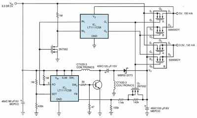
Simple Daul Regulator Handles Two Input Voltages
The circuit in Fig 1 supplies both 3.3 and 5V to transitional circuits that employ both the new 3.3V and older 5V devices. Additionally, because the regulator accepts either 3.3 or 5V inputs, you could plug it into either a new 3.3V system or an old 5V system.The circuit consists of two sections: a dc/dc converter and a double-pole, double-throw (dpdt) switch. The dpdt switch comprises a pair of dual n-channel MOSFETs (Q2 and Q3) and their associated high-side drivers.
Upon power-up, the comparator in IC2 determines the state of the circuit. The comparator’s output, IC2 pin 6, goes to the input of the MOSFET driver, IC1. The driver internally generates a gatedrive voltage 8.8V above the device’s supply voltage. This high voltage drives the appropriate MOSFETs in Q2 and Q3.
IC2 is also the heart of a flying-capacitor, buck/boost dc/dc converter. Unlike other switching-regulator schemes, this topology needs no transformers. Transistor Q1 controls this section’s output voltage, VS. When VIN is at 5V, Q1 is off, forcing the section to operate as a step-down converter. In this mode, the section produces 3.3V, which goes to the output through Q3B. Also in this mode, 5V power goes directly through Q2A, and Q2B and Q3A are both off.
When VIN is 3.3V, IC1 turns on Q1, shorting out the 140-kΩ resistor and forcing the dc/dc-converter section into step-up mode. In this mode the converter section generates 5V at VS, powering the 5V output via Q2B. Also in this mode, 3.3V goes directly from the circuit’s input to the output via Q3A. Q2A and Q3B are both off.No-load quiescent current consumption is approximately 500 μA.
Lower-frequency converters would reduce power consumption at the expense of a larger inductor. The efficiency of the dc/dc-converter section is 73% in either mode. But because this power accounts for only half of the circuit’s output power, the circuit’s overall efficiency is approximately 80% with VIN=3.3V and 86% with VIN=5V.
Lower-frequency converters would reduce power consumption at the expense of a larger inductor. The efficiency of the dc/dc-converter section is 73% in either mode. But because this power accounts for only half of the circuit’s output power, the circuit’s overall efficiency is approximately 80% with VIN=3.3V and 86% with VIN=5V.
Saturday, September 13, 2014
6 Input Mixer Schematics
Subscribe to:
Posts (Atom)

